Key Features of TITAN Engine S
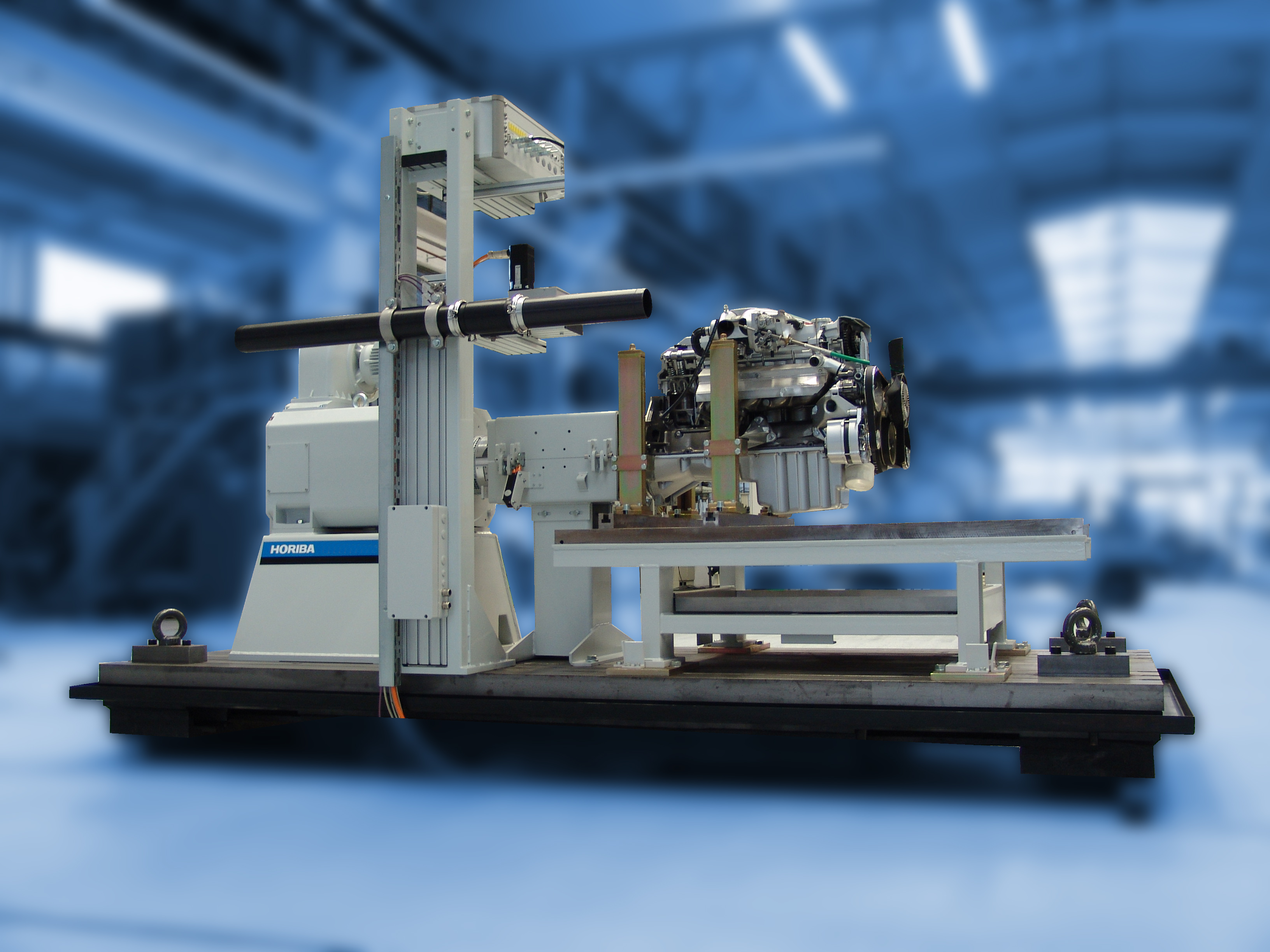
For other ranges of engines, the full range of HORIBA brakes and dynamometers can be combined with the extensive range of TITAN modules.
Examples for possible applications
- Steady-state engine testing
- Engine mapping
- Power measurement
- Durability testing
- Component testing
- Aging of catalysts
Benefits at a glance
- Attractive price to reduce investment costs
- Short delivery time actually 16 weeks ex works, to avoid bottlenecks in productivity
- Short installation and commissioning time - average 10 days for hand over to the user
- Easy integration in existing site installations - to save secondary investment
- Upgradeable in the future - for investment security and flexibility just in case your requirements change.
- Low cost of operation - to help decrease overall development costs
- Universal use of high quality components and advanced technology - for optimal handling and efficient use
Typical System Diagram
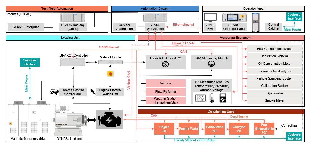
The TITAN Engine test cell can be devided in 6 areas:
- Loading Unit
- Conditioning Units
- Measuring Equipment
- Automation system
- Operator Area
- Test Field Automation
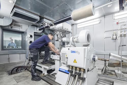
The engine (specimen) is connected to the engine dnamometer (dyno) – in in the example shown, a DYNAS3 load unit.
The dyno is powered by the variable frequency drive cabinets, that can be located in the test cell or outside the test cell, for example in the technical area.
The specimen inputs (such as throttle position) are sent and handled by the Automation System, such as the HORIBA STARS Engine. The STARS Workstation is in charge of handling all the measuring equipment, besides the dyno, such as the Fuel Consumption Meter, Oil Consumption Meter, Exhaust Gas Analyzers, Smoke Meter, Conditioning Units, etc.
The interface between the test cell operator and the Automation System is the STARS HMI PC and the SPARC Operator Panel.
Besides, the information from the test cell can be transferred to STARS Enterprise, for an efficient test lab data management and process automation.
