尺寸
5.24
MB
〈Catalog〉Industrial Water Quality Measuring Instruments
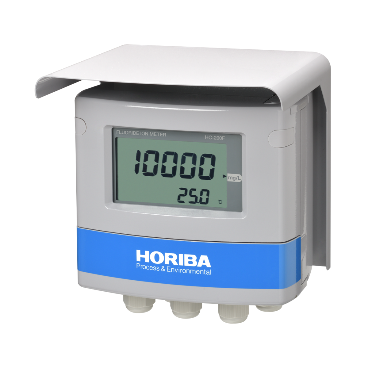
現場安裝型氟離子濃度計
![]()
![]()
![]()
![]()
![]()
![]()
![]()
Supporting a wide range
With a single unit, a wide range from low to high concentrations can be covered.
Comprehensive range of cleaning devices.
A diverse lineup of cleaning devices are offered.
| Product name | Fluoride ion meter | ||
|---|---|---|---|
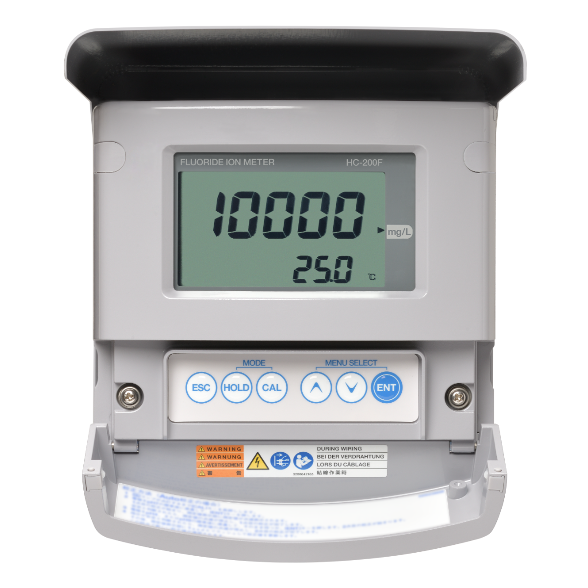
| Model | HC-200F | ||
| Electrode used with product | Fluoride ion electrode | ||
| Measurement range | Concentration | 0 mg/L to 10000 mg/L (Display range: 0 mg/L to 11000 mg/L) | |
| Available range options: 10000, 5000, 2000, 1000, 500, 200, 100, 50, 20.0, 10.0 mg/L | |||
| Temperature | 0℃ to 100℃ (Display range: -20℃ to 130℃) | ||
| Display resolution | Concentration | 0.1 mg/L: 0.0 mg/L to 20.0 mg/L 1 mg/L: 0 mg/L to 200 mg/L 10 mg/L: 0 mg/L to 2000 mg/L 100 mg/L: 0 mg/L to 10000 mg/L | |
| Temperature | 0.1℃ | ||
| Performance | Concentration | Repeatability | Within ±7% of the full scale (response for equivalent input) |
| Linearity | Within ±10% full scale (response for equivalent input) | ||
| Temperature | Repeatability | ±0.3℃ (response for equivalent input) | |
| Linearity | ±0.3℃ (response for equivalent input) | ||
| Transmission output | Number of output points | 2 (the negative terminals for transmission outputs are internally connected and at the same electric potential) | |
| Output type | 4 mA to 20 mA DC, input/output isolated type | ||
| Load resistance | Max.: 900Ω | ||
| Linearity | Within ±0.08 mA (output only) | ||
| Repeatability | Within ±0.02 mA (output only) | ||
| Output range | Output 1 | Concentration: Selection from preset ranges or free range input within measuring range. | |
| Output 2 | Temperature: Free setting within a range between -20℃ and 130℃ | ||
| Occasional out for error | Hold or burnout to either 3.8 mA or 21 mA | ||
| Transmission hold | In the maintenance mode, transmission signal is held at the latest value or preset value. In the calibration mode, transmission signal can be alive or held. | ||
| Contact output | Number of output points | 3 points | |
| Output type | No-voltage contact output | ||
| Contact type | Relay contact, SPDT (1c) | ||
| Output capacity | 250 V AC 3 A, 30 V DC 3 A (resistance load) | ||
| Contact function | R1, R2 | Selectable from upper limit alarm, lower limit alarm, ON/OFF control,currently holding of transmission output, and cleaning output (The contact is closed during alarm operation, opened normally and while the power is down). | |
| FAIL | Error alarm (Closed in the normal state, opened in the failure state or while the power is down.) | ||
| Alarm setting range |
| ||
| Control setting range |
| ||
| Cleaning output | Number of output points | 1 | |
| Output type | Contact output with voltage (output of connected power supply voltage) | ||
| Contact type | Relay contact; SPST (1a) | ||
| Contact capacity | 250 V AC 0.5 A | ||
| Contact function | Actuation of solenoid valve for cleaning | ||
| Settings | Cleaning period | 0.1 hours to 168.0 hours | |
| Cleaning time | 2 seconds to 600 seconds | ||
| Hold time | 2 seconds to 600 seconds | ||
| Timer accuracy | Within 2 minutes per month | ||
| Description of cleaning operation |
| ||
| Contact input | Number of input points | 1 | |
| Contact type | No-voltage “a” contact of open collector | ||
| Conditions | ON resistance: 100Ωmax. Open voltage: 24 V DC Short-circuit current: 12 mA DC max. | ||
| Contact function | External input for cleaning or transmission holding if cleaner is not attached. | ||
| Transmission capability | Communication type | RS-485 | |
| Signal type | 2 wire system, isolated from the input circuit Not isolated from transmission circuit | ||
| Temperature compensation | Applicable temperature element | Platinum resistor: 1 kΩ (0℃) Positive relation resistor with temperature: 10 kΩ (25℃) | |
| measurement range of temperature | 0℃ to 100℃ | ||
| Temperature calibration | 1 point calibration comparing reference thermometer | ||
| Calibration | Number of calibration points | Selectable from 1, and 2 points | |
| Kinds of standard solutions | The first point: Calibrated by the standard solution with the density from 50% to 100% of the measuring range. The second point: Calibrated by the standard solution with the density from 1% to 20% of the measuring range. | ||
| Additional capabilities | Automatic detection of calibration failure (asymmetry potential,sensitivity, or response time) Calibration history (asymmetry potential, sensitivity, and number of days elapsed after last calibration) | ||
| Self-check | Calibration error | Asymmetry potential error, and sensitivity error Temperature calibration error | |
| Electrode diagnostic error | Temperature sensor short-circuit, temperature sensor disconnection,and out of the temperature measurement range | ||
| Converter error | CPU error, ADC error, and memory errors | ||
| Operating temperature range | -20℃ to 55℃ (without freeze) | ||
| Operating humidity range | Relative humidity: 5% to 90% (without condensation) | ||
| Storage temperature | -25℃ to 65℃ | ||
| Power supply | Rated power supply voltage | 100 V to 240 V AC ±10% 50/60 Hz | |
| Power consumption | 15 VA (max) | ||
| Others | With power switch for maintenance use | ||
| Compatible standards | CE marking | EMC :EN61326-1 Class A, Indrial electromagnetic environmentust Safety :EN61010-1 RoHS :EN50581 9. Industrial monitoring and control instruments | |
| FCC rules | Part15 Class A | ||
| Structure | Installation | Outdoor installation type | |
| Installation method | Mounted on 50 A pole or wall | ||
| Protection code | IP65 | ||
| Case material | Aluminum alloy (coated with epoxy-denatured melamine resin) | ||
| Material of fittings | SUS304 | ||
| Material of hood | SUS 304 stainless steel (coated with epoxy-denatured melamine resin) | ||
| Material of window | Polycarbonate | ||
| Display element | Reflective monochrome LCD | ||
| External dimensions | 180 (W) × 155 (H) × 115 (D) mm (excluding mounting brackets) | ||
| Mass | Main body: Approx. 3.5 kg Cover and mounting brackets: Approx. 1 kg | ||
*: When the sensor cable, the transmission cable, or the contact input cable is extended to 30 m or longer, the surge test specified in the EMC directive for CE marking is not applied.
An arrester (spark over voltage: 400 V) is implemented for transmission output, contact input, and communication. However, use a most suitable surge absorption element on the connection lines in accordance with the ambient environment, the situation of equipment installed, and the externally connected equipment.
如您有任何疑問,请在此留下詳細需求或問題,我們將竭誠您服務。