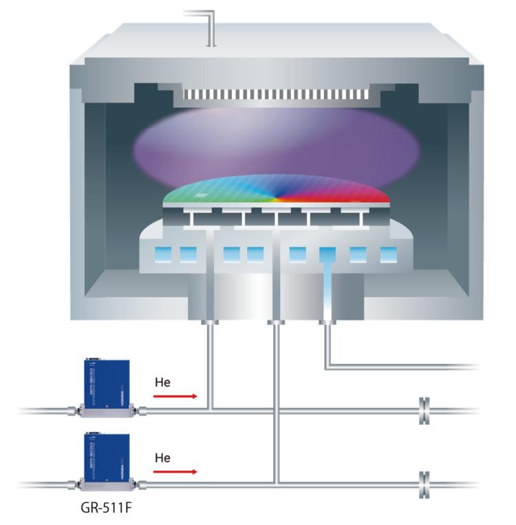
| Model | GR-511F |
| Valve Type | C: Normally close |
| Leak integrity | ≤ 7 × 10-11 Pa·m3 /s (He) |
| Maximum operating pressure | 300 kPa (A) |
| Pressure resistance | 350 kPa (A) |
| Operating temperature | 5-50 °C (Accuracy guaranteed temp : 15-40 °C) |
| Power supply | +15 VDC±5 %, 250 mA -15 VDC±5 %, 250 mA |
| Power consumption | 7.5 VA |
| Interface | Analog |
| Gas *1 | He, Ar, N2 |
| Standard fittings | 1/4 inch VCR or equivalent |
| Pressure full scale | 1.333 kPa (A) (10 Torr), 2.666 kPa (A) (20 Torr), 6.666 kPa (A) (50 Torr) |
| Pressure control range | 1-100 %F.S. |
| Pressure accuracy *2 | ±0.5 %R.S. |
| Zero temperature coefficient | ±0.04 %F.S./°C |
| Span temperature coefficient | ±0.04 %R.S./°C |
| Response *3 | ≤ 1 sec |
| Pressure setting signal | 0.1-10 VDC (1-100 %F.S.) Input impedance ≥ 1 MΩ Option:0.05-5 VDC (1-100 %F.S.) Input impedance≥ 1 MΩ |
| Pressure output signal | 0-10 VDC (0-100 %F.S.) Minimum resistance 2 kΩ Option:0-5 VDC (0-100 %F.S.) Minimum resistance 2 kΩ |
| Flow full scale *1 | 20, 50, 100 SCCM |
| Flow accuracy *4 *5 | ±1 %R.S. (Flow rate > 25 %F.S.) ±0.25 %F.S. (Flow rate ≤ 25 %F.S.) |
| Flow rate output signal | 0-5 VDC (0-100 %F.S.) Minimum resistance 2 kΩ |
| Wetted material | SUS316L |
| Mounting orientation *6 | Free |
| Weight *7 | 1.5 kg |
*1 Please consult about other specifications.
*2 Guaranteed only for STEC calibration condition.
*3 Guaranteed only for calibration gas (N2) and calibration condition. Depends on gas or usage condition, response time may be changed.
*4 Flow accuracy complies with SEMI E56-0309. Guaranteed for calibration gas (N2), full scale and pressure condition.
*5 A flow rate exceeding 100% F.S. cannot be guaranteed for accuracy.
*6 Please make a zero point adjustment for both pressure and flow rate in an actual-use environment to eliminate mounting operation effect.
*7 Reference value with standard fitting. ·In notation of pressure unit, (A) shows absolute pressure. ·SCCM is symbol representing the gas flow rate (ml/min, at 0°C 101.3 kPa) . ·F.S. is a percentage of the full scale and %R.S. is a percentage of the reading scale.
